![]()
![]()
![]()
![]()
![]()
![]()
Structural analysis and special foundations design
Geomechanics and geotechnical software
FINITE ELEMENT ANALYSIS
|
Why a F.E.M. algorithm?
|
|
|
Evolution of theories and calculations’ instruments allowed to introduce some decades ago the Finite Elements Method in the field of Soil Mechanics also. Approximate solutions obtained by simplified traditional methods, since then, must be regarded as somewhat “confidence assessments” respect to the up-to-date numerical solutions, being in facts justified by cultural inertness only, imparagonable with the real performances warranted by FEM techniques. As a first issue, the limit equilibrium solutions are in no way capable to assess any kind of dispacement inside the slope, before failure occurs and at failure. Also, in comparision, almost all the approximate traditional methods consider some pre-determined sliding surfaces inside the slope, exploiting repeated mechanical analyses over such surfaces only. |
|
In other words, only when the user inputs in advance a “good” surface (or a group of surfaces), a somewhat representative safety factor might be obtained.
FE methods, instead, enable focusing reliable solutions for each particular problem, in terms of displacements and safety factors, in facts the “true” solutions likely to occur for a specific site described in terms of geometry and soil parameters.
Further, seismic analyses based upon limit equilibrium are quite unreliable, being by definition uneffective every action not lying along a well defined failure surface. Earthquake accelerations occur in all directions, vertical as well as horizontal, resulting in complex paths instead. Also, they are variable with dept, according indeed with prescriptions of many building codes, and as resulting from many seismic site response analysis. All these feature can be easily accounted for in FEM approaches, in which well defined fields of accelerations can be applied, both horizontal and vertical, or in a combination of the two.
Taking in mind that the input for a FEM analysis is simple and based on items very similar to the ones for traditional methods, the user can experience a substantial difference in his own analyses.
![]()
The Finite Elements Method
FEA-Slope is an up-to-date very performing computer program for slope stability analysis, based upon a robust and sophysticated algorithm for Finite Element Analysis (F.E.A.).
The slope or wathsoever geotechnical system is modeled in eight-noded plane elements, having specific geotechnical and geometrical characteristics.
Geotechnical input is defined in terms of unit weight, cohesion, angle of internal shear, dilatancy, Poisson’s ratio and soil modulus.
Slope failure entails that a well defined failure criterion is exceeded, implemented by a proper non-associated function based on a non-linear visco-plastic algorithm.
The geotechnical analysis includes the followings:
- in soils, a Mohr-Coulomb failure function (criterion)
- in rocks, a Hoek-Brown model
- definition of a safety factor based on “safety reduction factor” (SRF) method
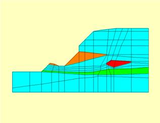
- geometry and displacements of the slope, before and at failure, enabling to detect “true” sliding surfaces likely to occur in facts
- reliable indications about where surfaces will possibly be located, also in order to install specific field instrumentation
- a tomography of the failure function based on Mohr-Coulomb criterion, showing soil masses yet subject to be instabilized in very first phases of soil displacements, and till complete failure is reached.
The geometry of the problem is defined by mean of an assisted input of points and quadrilateral elements, both as single or as complete under-meshes of finite elements. Triangular elements are allowed.
Groundwater conditions are described taking into account soil saturation and the actual terms of stress to be considered in every specific solution (total stresses or effective stresses).
Seismic analysis is carried allowing for horizontal as well as vertical acceleration fields, the latter both in upward and downward direction. Input of fields of accelerations variable in depth is allowed also, , according to the most recent domestic and international building ruling codes, see for exemple Eurocode’s prescriptions relevant to use of ST coefficient.
Computerized approach is developed in MS Windows environment and recall typical soil parametrization for slope stability problems. Soils are described in terms of resistance, deformability and dilatancy parameters as usual in F.E. for Soil mechanics, and managed by syntetic and clear dialog windows.
Reference manuals are clear and exhaustive, giving indications on how obtain all necessary geotechnical parameters.
|
|
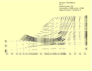
The solving algorithm is iterative, based on combination of FEM solution, theory of viscoplasticity and application of the SRF (strength reduction Factor) method in order to state safety against failure. In a first phase the slope is verified taking into account “characteristic” soil parameters, coming from soil investigations. Subsequently the soil resistance is factorized by increasing reduction factors and repeating the FEM viscoplastic calculations in turn, until failure is reached because soil parameters are too reduced to carry actual actions. Slope failure results from a sum of single plasticized elements, enough extended to form a continuous sliding surface. |
Slope is considered as failed if calculations don’t converge after a congruous number of iterations (suggeested 500 or more), namely the process of re-distribution of stress inside soil mass proves to be endless.
The “safety factor” Fs is then defined as the last SRF factor, in an ordinate increasing series, immedately preceding the one for which failure occurs.
|
|
|